Your vehicle's ignition switch is the nerve center of its electrical system. It tells your battery where to send power and when, using a specific sequence of connections. Getting familiar with terminals like BATT, ACC, IGN, and ST is the foundation for a successful wiring job.
How Your Ignition Switch Works
Before touching a wire, it's essential to understand what’s happening behind the dash. The ignition switch is a multi-stage rotary switch. Each click of the key closes a different electrical circuit, methodically bringing your vehicle’s systems to life.
These switches have been the primary electrical control in cars for decades, evolving from basic mechanical contacts to sophisticated components. Since around the mid-1900s, they’ve been the standard for controlling everything from the starter to the radio.
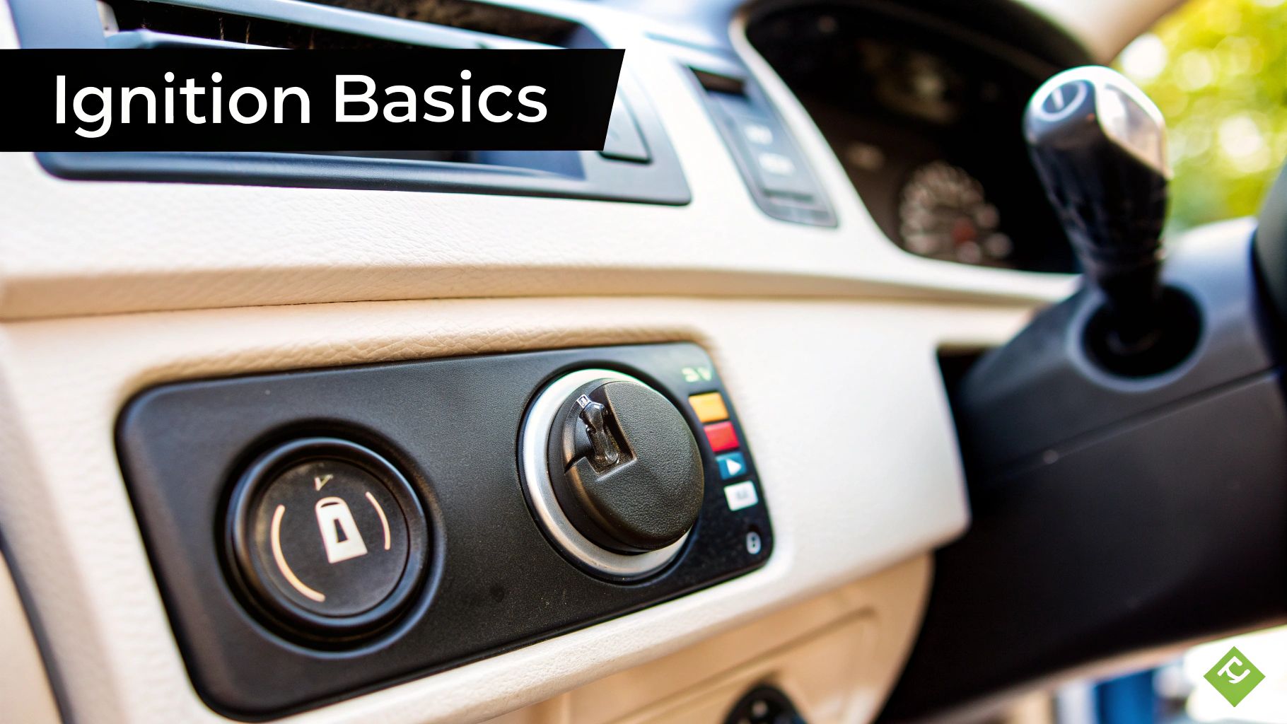
The Key Positions And Their Functions
Every key position serves a distinct purpose. That first click is typically the accessory circuit, or ACC. It powers comforts like your stereo without the engine running.
Turn the key one more notch to the "run" position, and you engage the ignition circuit (IGN). This is a big one. It sends power to critical systems needed to run the engine, like the fuel pump, ECU, and dashboard.
The final turn engages the start circuit (ST). This position directs a heavy flow of power straight to the starter motor. This cranks the engine over.
This sequence is common for most cars and trucks, but specifics can vary. For boats, the principles are similar but components differ. You can find more details on that here: https://boating-articles.com/2025/07/26/installing-marine-electronics/
Common Ignition Switch Terminal Functions
To make sense of the wires, it helps to know what each terminal does. This table breaks down common abbreviations.
| Terminal Abbreviation | Full Name | Primary Function |
|---|---|---|
| BATT | Battery | Receives constant 12V power directly from the battery. |
| ACC | Accessory | Powers non-essential accessories like the radio and windows. |
| IGN | Ignition | Powers essential engine systems like the fuel pump and ECU. |
| ST | Start | Sends power exclusively to the starter motor to crank the engine. |
Knowing these terminals is crucial. Hooking up the wrong wire can cause things not to work or damage components. Always double-check your connections.
Setting Up for a Safe and Successful Wiring Job
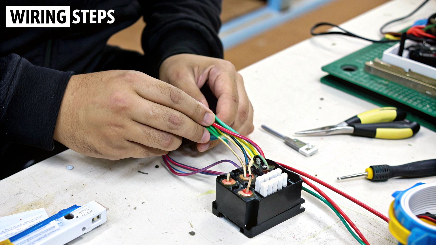
Before touching a wire, the real work begins with proper prep. A clean, successful wiring job is all about what you do beforehand. Gathering the right tools and securing your workspace prevents frying your vehicle's sensitive electronics.
Having the right gear on hand makes the process smoother. You'll need more than a basic socket set for this kind of electrical work. Three specific tools are essential for secure connections and accurate diagnostics.
- Digital Multimeter: This is your best friend for testing continuity and verifying power.
- Quality Wire Strippers: A good set of strippers cleanly removes insulation without nicking delicate copper strands.
- Proper Crimpers: A dedicated crimping tool creates a strong, mechanical bond that won’t vibrate loose.
Safety First, Always: Before starting, there's one non-negotiable step. Disconnect the negative terminal from your vehicle's battery. This simple action prevents accidental short circuits that can destroy components or cause serious injury.
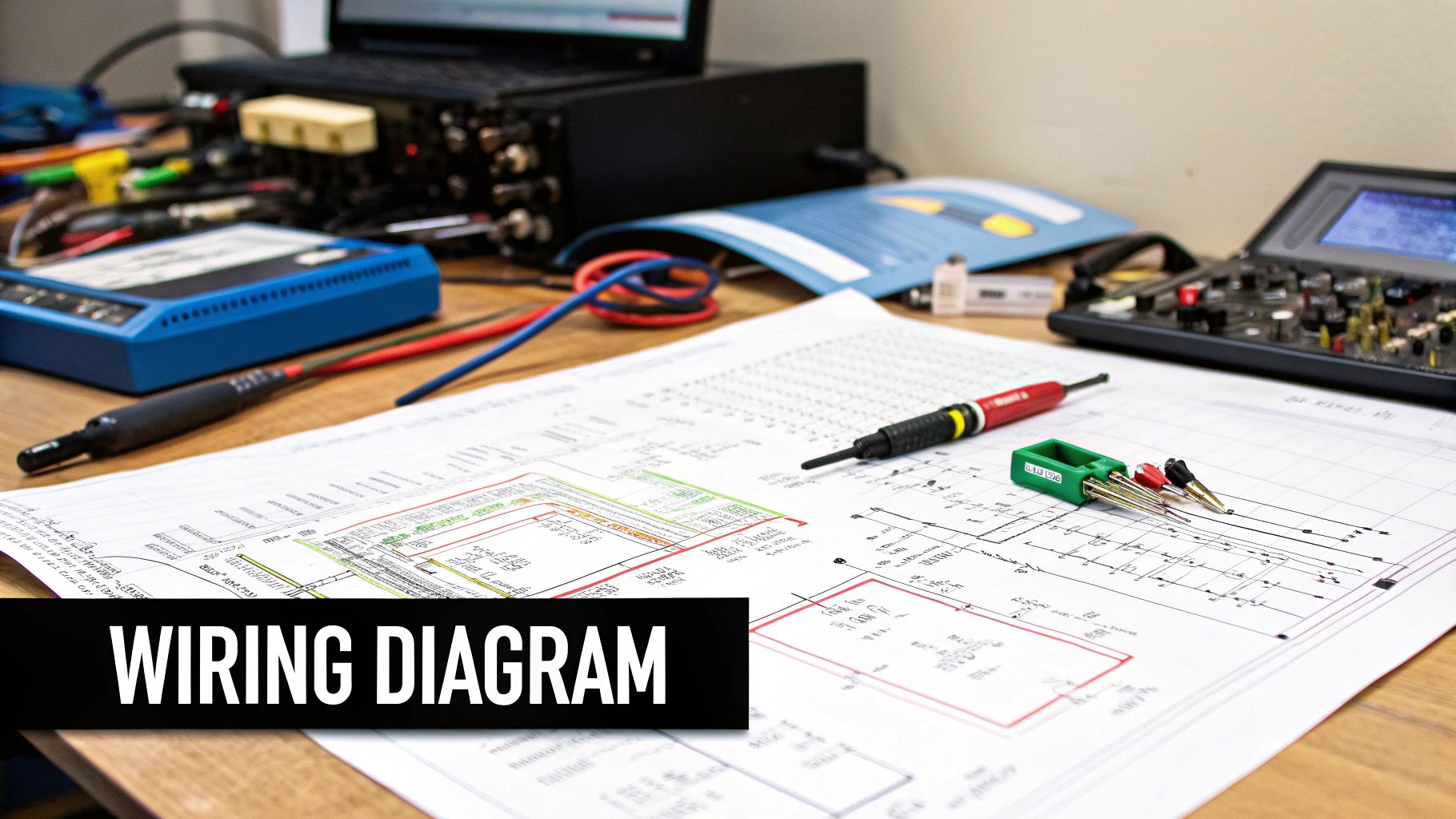
Making Sense of Your Vehicle's Wiring Diagram
A wiring diagram can look like a jumble of lines and symbols. It is easy to feel overwhelmed. But think of it as a detailed road map for every wire in your vehicle.
Let's break down how to read one.
The most critical first step is getting the correct diagram for your vehicle's year, make, and model. A generic one can create a massive headache, as manufacturers often change wire colors and layouts. Check factory service manuals or dedicated online forums for your specific vehicle.
Decoding the Language of Lines and Symbols
Every line on the diagram is a real wire in your vehicle. The wire's color is usually abbreviated next to the line. For example, you’ll see codes like "BLK" for black or "GRN/YEL" for a green wire with a yellow stripe.
You'll also see symbols scattered around representing different electrical parts. Getting familiar with them is key to tracing a wire's complete path.
Here are a few common ones you'll encounter:
- Fuses: These look like a small rectangle or a squiggly S-shaped line.
- Switches: Typically drawn as a broken line with a hinge, showing how a circuit can be opened or closed.
- Grounds: This return path to the battery looks like a stack of shortening parallel lines.
A classic rookie mistake is confusing a wire junction with a crossover. A solid dot where lines intersect means the wires are electrically connected. If lines just cross with no dot, they are not connected at all.
Tracing the Ignition Circuit Step-by-Step
Once you have the right diagram, find the symbol for the ignition switch itself. You'll see several wires branching out from it. Each one heads off to power different systems.
Your job is to trace the key circuits. Start by finding the main power wire from the battery, likely labeled "BATT". Then, patiently follow the lines for the accessory (ACC), ignition (IGN), and starter (ST) circuits.
Making Solid and Reliable Wire Connections
The success of your ignition switch wiring comes down to the quality of your connections. A sloppy crimp or exposed wire can cause frustrating electrical gremlins later. The goal is to make every connection as good as the factory produced.
It all starts with a clean wire strip. Use a proper wire stripping tool to remove about a quarter-inch of insulation. Be careful not to nick or cut any of the fine copper strands underneath.
Crimping Versus Soldering
Once your wire is prepped, you must join it to a terminal or another wire. For most automotive jobs, a high-quality crimp is the best choice. It creates a solid mechanical bond that holds up to engine vibration.
Soldering creates a fantastic electrical connection, but it makes the wire rigid at the joint. Over time, that stiffness can lead to the wire becoming brittle and cracking.
- Crimping: Always use a dedicated crimping tool for a secure connection.
- Soldering: This is better for stationary electronics, not high-vibration engine bays.
The demand for reliable wiring components is significant. The U.S. wires and cables market was valued at USD 31.78 billion in 2024, driven by complex vehicle electrical systems. If you're interested in the numbers, you can explore the full market analysis here.
Pro Tip: Never call a connection finished until you've sealed it with heat shrink tubing. Slide a piece over the crimp, apply heat, and watch it shrink to form a tough, moisture-proof seal. This small step prevents corrosion and separates an amateur job from a professional one.
These principles apply to almost any wiring job, including marine applications. We have a whole guide on the specifics of bilge pump wiring if you work on boats.
Troubleshooting Common Ignition Wiring Issues
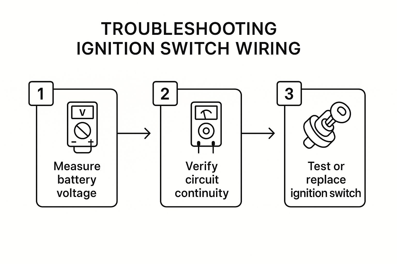
The feeling when you turn the key and get silence is all too familiar. The culprit is often hiding in the ignition switch wiring. A methodical approach can save you a world of frustration.
Let’s walk through a classic scenario: your radio works, but the engine won’t crank. This clue points to the ST (Start) circuit. Grab your multimeter and check for 12 volts at the start terminal on the switch while a helper holds the key in the "start" position.
If you see voltage, the switch is working, and the problem is elsewhere. No voltage? The switch is likely the problem.
Finding The Root Cause
What if the engine cranks but won’t start? This tells a different story. The starter circuit is working, but the IGN (Ignition) circuit isn't powering components like the ignition coil or fuel pump.
In this case, check for voltage at the IGN terminal when the key is in the "run" position. This diagnostic flow chart simplifies how to approach an ignition switch problem.
By starting with the basics, you can quickly pinpoint if the ignition switch is the source of your headache. To help diagnose issues faster, here's a table connecting common symptoms to likely wiring problems.
Common Ignition Issues and Potential Wiring Causes
| Symptom | Potential Wiring Culprit | First Diagnostic Step |
|---|---|---|
| Engine won't crank, no click | No power to the ST terminal or a bad switch | Check for 12V at the ST terminal with the key in "start" position. |
| Cranks but won't start | No power from the IGN terminal | Check for 12V at the IGN terminal with the key in "run" position. |
| Engine dies when key is released | Faulty internal connection between ST and IGN | Test continuity between the BATT and IGN terminals in the "run" position. |
| Accessories don't work | No power from the ACC terminal | Check for 12V at the ACC terminal with the key in "accessory" position. |
This table should get you pointed in the right direction. Remember that wiring can be tricky, and a multimeter will be your best friend.
A dead circuit often comes down to a simple break. Use your multimeter's continuity setting to check the wire between the switch and the component. If you get a reading of OL (overload or open line), you've found your broken wire.
These troubleshooting basics apply to almost any vehicle. If you're on the water, our guide on boat motor troubleshooting offers more detailed advice.
Frequently Asked Questions About Ignition Wiring
Diving into an ignition wiring project can bring up some tricky questions. Let's tackle a few of the most common ones.
Can I Use an Aftermarket Ignition Switch?
Absolutely. Using an aftermarket ignition switch is standard, especially for custom builds or older vehicles.
The most important thing is to match the new switch's functions to the old one. You'll need to identify the terminals for BATT, ACC, IGN, and ST. Then, carefully map the wires from your harness to the correct posts.
Be aware that terminal labels aren't always universal. Always check the paperwork that came with the new part to avoid guesswork.
A word of advice: don't cheap out on the switch. I've seen low-quality aftermarket units fail prematurely. Spending a few extra bucks on a switch from a reputable brand can save you from doing the same job twice.
Why Does Wire Gauge Matter So Much?
Getting the wire gauge right is non-negotiable for performance and safety. A wire is a pipe for electricity and must be thick enough to handle the current without getting hot.
The beefy wire to your starter solenoid handles a massive load, while a cabin light wire carries very little. Using a wire that's too thin for the current is a serious fire hazard.
An undersized wire also causes a "voltage drop," meaning components won't get full power. This can lead to weak starts, dim lights, or electronics that won't turn on. When in doubt, match or go one size thicker than the original wire.
For more expert guides and in-depth articles on everything from electrical work to engine maintenance, visit Boating Articles. Our step-by-step instructions and practical advice are designed to help you tackle any project with confidence. https://boating-articles.com